Loop Tools
Activation
Open Blender and go to Preferences then the Add-ons tab.
Click Mesh then Loop Tools to enable the script.
Description
Bridge
There are two main ways to use the Bridge tool. The first method is to select two groups of faces and then run the tool. The second method is to select two (closed) loops of edges. Both methods can be mixed and you can even Bridge multiple groups at the same time. The script will try to make an educated guess on which groups should be connected.
Bridge shares its settings with the Loft tool, so changing a setting for one of the tools, will also change it for the other tool.
The number of faces used to bridge the distance between two loops. One segment means that only faces will be created. Two (or more) segments means that an intermediary line (or lines) of vertices is created, so two or more faces can be defined between the loops. If the value is set to zero, the script automatically calculates the best amount of segments in order to keep the faces as square as possible.
This option has no label, but is located directly to the right of the segments setting. The simple explanation: 0% lot of triangles, 100% mostly square faces. There is a bit more to it though. It determines when a new vertex has to be created, or when to use the vertex next to it. It does this based on the distance between these vertices compared to the distance between the vertices in the original loops. So 50% means that if the distance between two vertices that will be newly created is smaller than half the distance between two vertices in the original loop, they will be merged together, resulting in only a single new vertex. This is also demonstrated in the video above.
This can be set to either cubic or linear. Linear is just a flat interpolation, while cubic tries to retain the surface tangents, resulting in more fluid curves.
The strength option is only available when the interpolation mode is set to cubic. Setting the strength to zero gives a result very similar to linear interpolation, while higher strengths result in more fluid curves. Setting a negative strength changes the direction of the curve. Or described in a more visual way: it makes deflated volumes inflate and vice versa. The soft limits of this option are set to range from -3 to +3, but you can easily assign bigger or smaller values by manually entering a number, instead of using the slider. This works just the same as with normal sliders in Blender.
When using a face-selection input, the inner faces will be removed after bridging.
Because of some limitations in Blender the weight values assigned to the Bevel modifier might be slightly altered (by about 0.01) when this option is enabled.
Determines which vertices in both loops are connected to each other. This might be used for artistic reasons or to correct a wrong result given by the script.
This option should only be used if the script gives a wrong result. It reverses the order in which vertices are connected and can fix problems when the script gives a result that looks inverted. It’s a bit hard to describe, but just try it once and you’ll immediately understand what it does.
Creating Holes
You can additionally create holes in an object via the Bridge tool. Select two or more faces and run the Bridge tool.
Circle
There are two correct inputs for the circle tool: selecting a single vertex, or selecting a closed or open loop of edges. You can also have the tool operate on multiple inputs at the same time and mix the input types.
Method Best Fit
When Best Fit is selected a circle is calculated using a non-linear least squares method. This basically means that the circle that is calculated with this option best fits the vertices you selected.
Selecting Fit Inside will calculate the circle in such a way that none of the vertices will be moved away from the center of the calculated circle. This is useful when you want to retain the topology of the surrounding mesh.
When enabled, the input will be flattened to an optimal plane. This includes the center vertex, if the input consisted of a single vertex. When disabled the input will be projected onto the existing mesh.
This overrides the radius calculated by the script. Useful if you wish to create several circles of the same size, or if you need more precision.
When this option is selected, the vertices on the circle will all have the same distance between each other.
The force of the tool. Zero percent influence means no changes will be made to the mesh. 100% influence means that the input will be fully transformed into a circle.
Curve
There are two valid input methods for the curve tool. The first is to select two or more vertices on the same loop. You can do this for multiple loops simultaneously to save time.
The second method is to select one or more entire loops. If a full loop is selected, the curve tool won’t operate on that loop, but on all loops perpendicular to it and use the vertices on the selected loop(s) as control points.
Cubic gives a smooth curve, calculated using a natural cubic spline algorithm. Linear calculates straight lines through the control points.
This restricts the movement of the vertices to only one direction. Indent only allows movement toward the mesh, while extrude only allows movement away from the mesh (in the direction of the normal).
If enabled, the curve won’t stretch beyond the input vertices. This limits the tool to only a subsection of the mesh.
This will evenly distribute the vertices along the curve. Sometimes this can create weird results, as an even distribution isn’t always possible (since the selected input vertices aren’t moved). If that is the case, simply uncheck this checkbox.
The force of the tool. Zero percent influence means no changes will be made to the mesh. 100% influence means the tool will have the maximum effect.
Flatten
Any selection is considered acceptable input for the flatten tool.
The method used to calculate the plane on which the input is flattened.
Calculates a plane so that on average the vertices will have to be moved the least to be flattened.
Is identical to scaling the input to zero on local Z when the orientation is set to normal (so G Z Z 0 ). It’s mainly included for making an easy comparison between the flatten methods.
Flattens the input on a plane perpendicular to the viewport angle. So when you run the tool, it will appear nothing has changed, but when you rotate the viewport, you’ll see what has happened.
The force of the tool. Zero percent influence means no changes will be made to the mesh. 100% influence means the input will be fully flattened.
Loft
For loft you can use the same input method as for Bridge: selecting groups of faces, or selecting (closed) loops. You can mix input methods. Contrary to Bridge, you can select more than two input groups, and have them bridged consecutively.
Loft shares its settings with the Bridge tool, so changing a setting for one of the tools, will also change it for the other tool. For a full discussion of all the settings take a look at the Bridge settings. Below you’ll find some specific information for the loft tool.
This is identical to the Segments setting of the Bridge tool, but setting it to automatic (segments = 0) has an advantage for the loft tool. When letting the script determine the number of segments needed, it might create different numbers of segments between different loops.
Connects the first and the last loop to each other.
Relax
The input of the relax tool consists of a single (partial) loop.
Determines how the final position of the vertices is calculated. Cubic uses a natural cubic spline to project the vertices on, linear projects the vertices on straight lines.
A word of caution: when you use the relax tool on a closed loop (a loop where all vertices are connected to two other vertices in the same loop) you can better use cubic interpolation instead of the linear. If you use linear interpolation, the volume of the loop will quickly diminish.
When set to Selection the tool will only operate on the selected vertices.
Setting it to Parallel (all), will also include the vertices of all parallel loops.
The number of times the tool is run. A higher number gives a smoother result.
If this option is selected, the vertices will be distributed evenly along the loop.
Space
The input of the space tool consists of a single (partial) loop.
Cubic distributes the vertices along a natural cubic spline through, while linear projects the vertices on the already existing edges.
When set to Selection the tool will only operate on the selected vertices.
Setting it to Parallel (all), will also include the vertices of all parallel loops.
The force of the tool. Zero percent influence means no changes will be made to the mesh. 100% influence means the tool will have the maximum effect.
For an illustrated explanation of all the tool settings visit the script homepage.
Please see the old Wiki for the archived original docs.
Mesh modeling toolkit. Several tools to aid modeling.
3D Viewport ‣ Sidebar ‣ Edit tab , 3D Viewport Edit Mode ‣ context menu
This add-on is bundled with Blender.
© Copyright : This page is licensed under a CC-BY-SA 4.0 Int. License. Last updated on 10/17/2021.
Источник
Трудности и «глюки», возникающие у новичков в программе Blender, и как их преодолеть
Blender это замечательный бесплатный 3d пакет, который делает возможным и доступным осуществление гигантского количества проектов, и, как человек, прошедший путь от абсолютного новичка в 3d до преподавателя данной программы в учебном центре «Специалист» в Москве, я могу поделиться несколькими типами, которые помогут преодолеть несколько несложных, но каверзных моментов, которые хоть и очень просты, но далеко не очевидны, и могут заставить просидеть несколько часов в поиске решения проблемы.
Перевод программы и подсказок
Перевод программы и подсказок — Blender, как и почти все программы является англоязычной, но в настройках (preferences) мы можем сделать его интерфейс русскоязычным. Переводить его полностью на русский язык я бы не советовал, т.к. названия всех терминов и команд почти необходимо знать на английском языке для дальнейшего развития, и, так или иначе, много из них заимствовано великим и могучим русским языком и используется всеми и повсеместно (нормали, фейсы, вертексы и т.д.). А вот перевод подсказок действительно может упростить процесс входа в программу и снять много вопросов в процессе их появления. Окошко с подсказкой возникает при наведении курсора мыши на любой элемент blender.
Для того чтобы активировать подсказки, если они не работают, нужно зайти в меню Edit-Preferences-Interface. Поставить галочку напротив Tooltips.
Для активизации перевода подсказок в том же разделе открываем выпадающее меню Translation, ставим русский язык, и галочку напротив Affect Tooltips.

Забагивание области просмотра
Следующая проблема с которой я постоянно сталкивался это забагивание области просмотра — при попытке панорамировать вид\приблизиться\отдалиться от объекта, blender упорно отказывается это делать, точнее делает это очень медленно . Тут помогает функция Frame, которая перезахватывает выбранный объект во вьюпорте и данная проблема устраняется.
Находится эта функция в меню View-Frame selected.

Clipping
Некст проблема это clipping — при попытке работать с объектом на близком расстоянии область обрезает часть нашего объекта, и мешает нам работать.
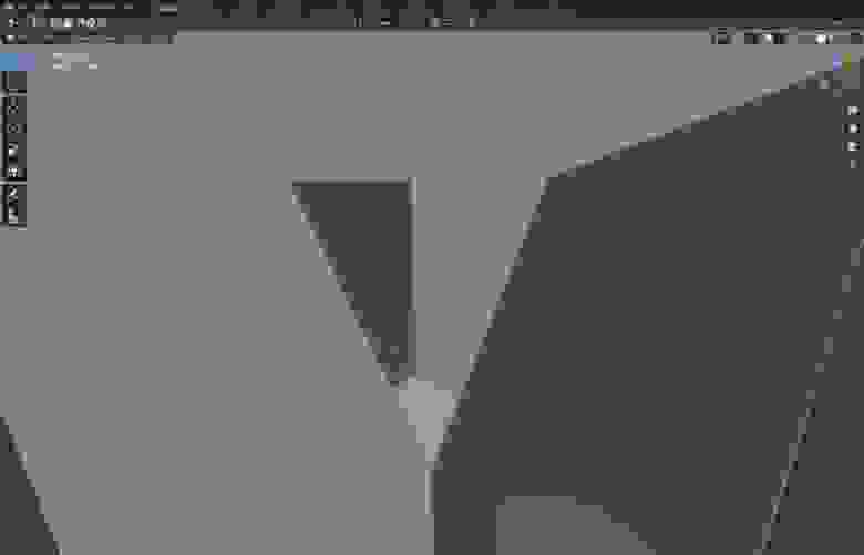
устраняется заходом в боковое меню нажатием кнопки N, и во вкладке view в выпадающем меню view, уменьшаем значение Clip Start (Например 0,001)

Нормали
Следующая проблема это нормали — будь то незнание того — что это? или незнание того — как их привести в правильное положение. Проблемы с нормалями возникают например при попытке запечь карты деформации, во время скульптинга, при попытке нажать Shade smooth и тд.
-Нормали это вектор перпендикулярный плоскости полигона, который указывает блендеру куда ему отражать свет. Направлен этот вектор только в одну сторону, то есть если нормаль вашего полигона развернута внутрь объекта, как часто случается в blender, то из за этого у вас будут проблемы на каком-то этапе работы.
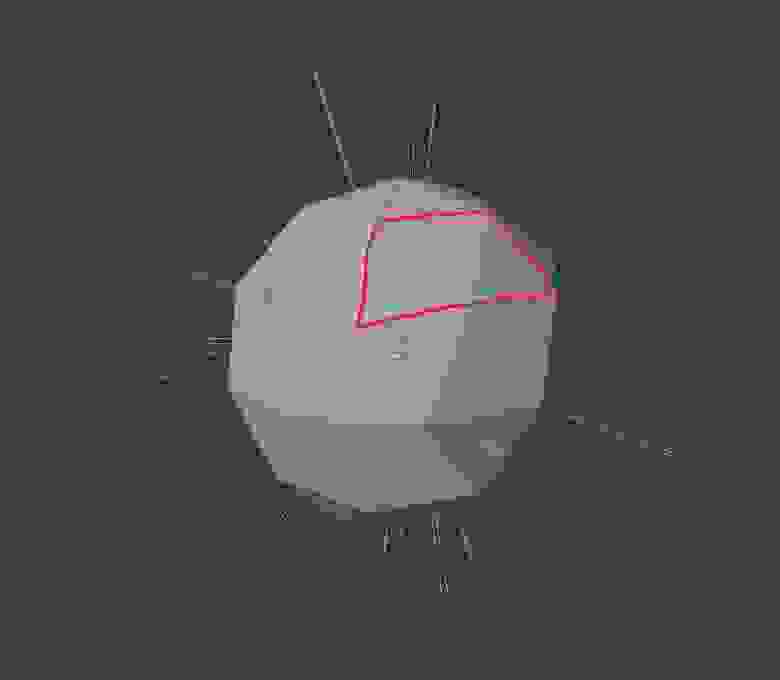
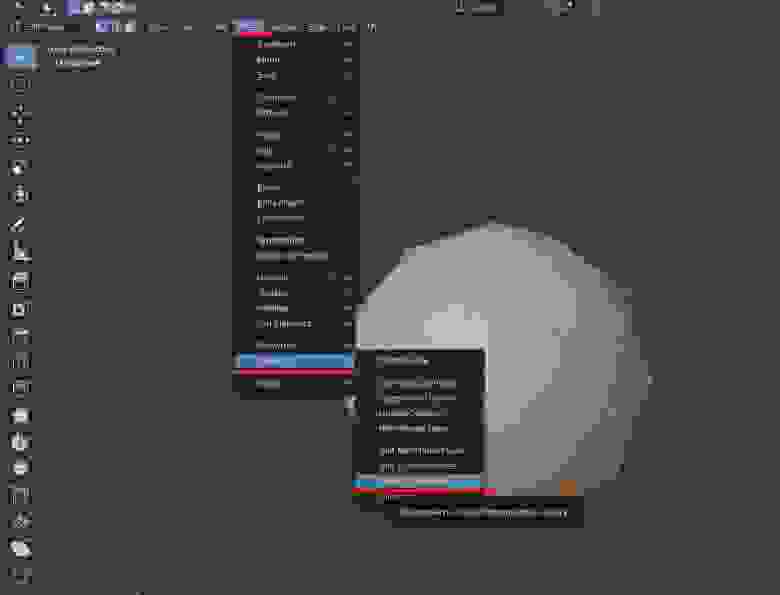
Как мы можем видеть на данном изображении — все нормали объекта, кроме трех выделенных, повернуты наружу, а три выделенные — внутрь. При обычном режиме затенения Shade flat — этого не видно, но если я включу режим затенения shade smooth, то результат будет совсем иным.
Проверить направление нормалей своего объекта я могу перейдя в edit mode, и в выпадающем меню overlays поставить галочку напротив Face orientation . Тогда все нормали повернутые наружу будут отображаться синим цветом, а направленные внутрь — красным. В этом же меню Overlays я могу включить отображение нормалей как векторов.

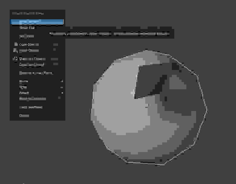
Развернуть нормали нам помогут функции Mesh-Normals-Flip (или recalculate outside)
Flip — развернет выделенные полигоны.
Также мы можем выделить все полигоны объекта (шорткат А) и нажать Recalculate outside чтобы blender автоматически пересчитал все наши полигоны наружу.
За направлением нормалей лучше следить.
Двойные вертексы
Двойные вертексы — часто в процессе моделирования и оперирования командой Extrude могут создаться вертексы, которые стоят друг в друге и будут портить нашу топологию, это может нам аукнуться на этапах UV развертки, создания рига и тд. Чтобы избежать этого, на промежуточных этапах работы можно выделять всю свою модель в режиме работы с вершинами и нажимать Mesh-clean up-merge by distance. Двойные вертексы будут объединяться.
Карты нормалей
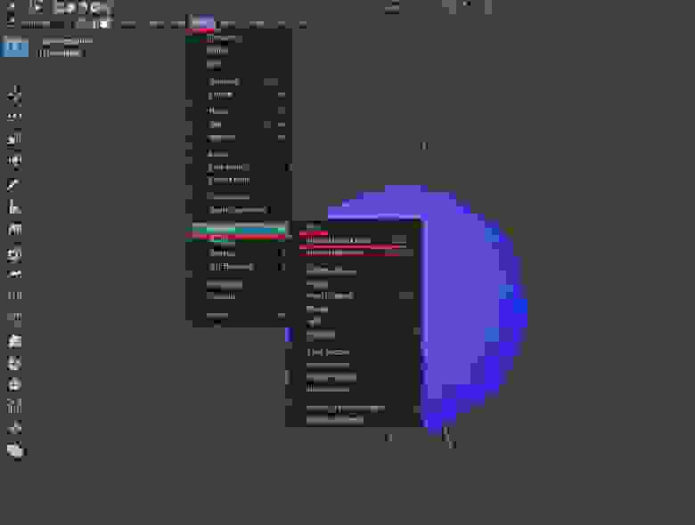
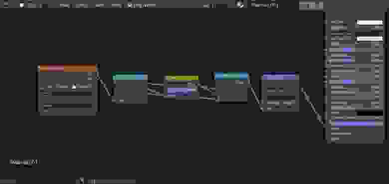
Карты нормалей запеченные в других программах (substance painter, Zbrush) дают странный результат в Blender .
Проблема в том что карты нормалей, в вышеперечисленных, и не только, программах, запекаются c использованием DirectX, а blender работает с OpenGL. Если говорить простым языком то нам нужно развернуть зеленый канал на карте нормалей. Делается это следующим образом:
Надеюсь, что данный пост поможет людям, осваивающим блендер, проскочить несколько часов поиска решения проблем!
Источник