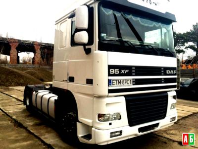
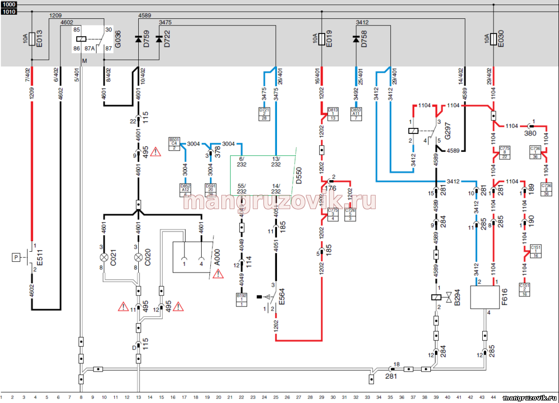
DAF 95XF электрическая схема стоп сигналов и горного тормоза.
легенда к схемам Даф 95 ХФ стопы и горный тормоз,указаны номера проводов,разъемов, штекеров,реле,предохранителей,выключателей, клапаны,точки соединения массы,розетки полуприцепа.
Перевод с немецкого языка пояснения к электрической схеме DAF 95XF
A000 розетка прицепа / полуприцепы ( 7 полюс) 62/63/230/241/284/399 E013 резервного тормоза фары 280 E019 предохранитель / CTE Индикаторы / направления / тормоз двигателя 35 E030 предохранительГорный тормоз 762 G036 реле стоп сигналов , 1 280/281 D759 диод предотвращения обеспечения скачка напряжения в стоп-сигналы 286 D722 диод стоп-сигналы , D758 диод предотвращая подачу скачка напряжения для CWS 291 E511 приведения в действие выключателя стоп-сигнал 280 C020 дополнительный стоп-сигнал , левый 281 C021 дополнительный стоп-сигнал , правый 283 D550 электронный блок управления КТР — 2 49 Е564 приведения в действие переключатель тормоз двигателя 64 G297 реле пневматическая подвеска кабины 288/291 B294 клапан выключения подвески кабины , высокий контроль Кабина Front 288
DAF (ДАФ) цифровая и цветовая маркировка проводов в электрических схемах Цветовая маркировка проводов автомобиля DAF, состоит из кодировки цветовой и числовой классификации проводов в следствии чего возможно избежать ошибки при выполнении соединений и ускорить время поиска неисправности.Кодирование состоит из четырех цифр, первая из них соотносится к основному цвету и группе.
14. BRAKE LIGHTS / CAB AIR SUSPENSION BRAKE LIGHTS
If the brake pedal is pressed, brake light control switch E511 is activated and the relay (G036) will be activated. A voltage will be applied to the right- and left-hand vehicle brake lights (C021 and C020 respectively) and they will light up. The lights connected through trailer connector socket A000 will also light up. A voltage will also be applied to the CTE unit (13/232) through diode D722. A voltage is also applied to connection point 5 of relay G297 (cab air suspension) through diode D759. CONTINUOUS BRAKE (engine brake) If the engine brake control switch (E564) is activated, a voltage is applied to connection point 14. As a result, connection point 55 is activated causing engine brake valve B192 to become activated. Connection point 55 is only connected to the supply voltage if: — The engine speed exceeds 700 rpm. — The rear wheels do not block in an ABS-equipped vehicle. CAB AIR SUSPENSION A voltage is applied to both the cab lock sensor (F616) and relay G297 through fuse E030 and wire 1104. If the cab is tilted, points 2 and 4 in the cab lock sensor (F616) are connected. As a result, relay G297 (cab air suspension relay) is activated through wire 3412 and the cab lock sensor (F616). The contacts of relay G297 close (connection between contacts 3 and 5). A voltage is now applied to valve B294 causing this valve to become activated as well. VARIANTS Location 12,14,16 Connector 495 is only used in the case of an FA version. In FT versions, wire 4601 (to C021 and C022) and earth do not run through connector 495. 20 Connector A000 is only used in the case of an FA. In FT versions, connector A002 is used.
Автомобильная диагностика — которой я пользуюсь. Смотреть в Youtube
Всякие АвтоХитрости по различным моделям.
Электро схемы, штекерные соединения, места установок.
Б/У автозапчасти для грузовиков.
Присоединяйся ко мне!
суббота, 4 мая 2013 г.
DAF CF65/75/85 Стоп-сигналы / наклон кабины
15 STOP LIGHTS/CAB TILTING GEAR STOP LIGHTS When the brake pedal is pressed, the stop light control switch E511 is activated (connection between contacts 2 — 1) and the relay (G036) will be energised. There is also a voltage on F628. Through fuse E013, wire 1209, contacts 30 and 87 of relay G036 and wire 4601 a voltage is now applied to the right stop light (C021) and the left stop light (C020), so that they go on. The lights that are connected via the trailer plug socket A000 will also go on. When relay G036 is energised, the connection 30 — 78a is broken. The voltage on D814 (UPEC electronic unit) or D903 (ECS-DC3 electronic unit) is lost. CAB TILTING GEAR There is a voltage on sensor F676 (cab locking sensor) and on sensor F616 (cab tilting cylinder sensor) through fuse E018 and wire 1114. There is also a voltage on connection point 2 of sensor F676 through connection points 1 — 2 of relay G351 (cab tilt protection microrelay) and wire 4723. When this sensor is activated, the voltage is transmitted to connection point 16 of D900 (VIC) and to connection point 2 of sensor F616. The VIC now sends a message to the DIP that then activates the “cab tilted” warning light. When sensor F616 is activated, relay G351 is energised and, as a result, a voltage is applied to B251 through contacts 3 and 5 and wire 4722 (neutral position buzzer, tilting cab). If the contacts in switch E569 (neutral position switch) are closed (connection between pins 4 — 2), the horn will go off. VARIANTS Location 9 Depends on whether the vehicle has a UPEC or ECS-DC3 engine. 12, 15 Connector 642 if FA type vehicle. 21 Depends on whether the vehicle has a 7-pin or 15-pin socket. See sub-diagram 47.
 Та информация которая описана в блоге — по сей день держится в секрете на станциях СТО. Это и не удивительно — ведь она стоит немалых денег. Увидев нелегкую жизнь дальнобойщиков, я создал блог чтоб открыть секреты, без которых в дороге — просто не обойтись (да и не только в дороге). Не верите — посмотрите!.________________________-/-И помните: Авторское право принадлежит блогу © «Автозапчасти и АвтоХитрости» и разрешено лишь копирование рисунков и схем! Переход на главную страницу.