- Настройка Cisco Nexus N3K-C3064PQ-10GX
- Настройка и проверка значения максимального блока передачи данных на платформах Cisco Nexus
- Параметры загрузки
- Об этом переводе
- Содержание
- Введение
- Предварительные условия
- Требования
- Используемые компоненты
- Настройка
- Конфигурации MTU уровня 3
- Настройка MTU на коммутируемом виртуальном интерфейсе (SVI)
- Настройте MTU на порте уровня 3
- Конфигурации MTU уровня 2
- Настройка MTU для политики качества обслуживания сети
- Настройка MTU на отдельных портах
- Настройка Nexus 2000
- Настройка FPC на отдельных портах (настраивается на родительском коммутаторе Nexus)
- Nexus 7000 / Конфигурация Кадра большого размера FEX (только применяется к версии 6.2 и позже),
- Настройка политики качества обслуживания сети (настраивается на родительском коммутаторе Nexus)
- Проверка
- MTU уровня 3
- MTU уровня 2
- Проверьте MTU на коммутаторах то QoS сети использования
- Проверьте MTU на коммутаторах та поддержка для каждого порта MTU
- Nexus 2000
- Устранение неполадок
- Влияние
- Cisco Nexus 5000 Series NX-OS Software Configuration Guide
- Book Title
- Chapter Title
- Results
- Chapter: Configuring the Switch
- Configuring the Switch
- Image Files on the Switch
- Starting the Switch
- Boot Sequence
- Console Settings
- Upgrading the Switch
- Upgrade Procedure Summary
- Detailed Upgrade Procedure
- Downgrading from a Higher Release
- Initial Configuration
- Configuration Prerequisites
- Initial Setup
- Preparing to Configure the Switch
- Default Login
- Configuring the Switch
- Changing the Initial Configuration
- Accessing the Switch
- Additional Switch Configuration
- Assigning a Switch Name
- Configuring Date, Time, and Time Zone
- Adjusting for Daylight Saving Time or Summer Time
- NTP Configuration
- About NTP
- NTP Configuration Guidelines
- Configuring NTP
- NTP CFS Distribution
- Enabling NTP Distribution
- Committing NTP Configuration Changes
- Discarding NTP Configuration Changes
- Releasing Fabric Session Lock
- Database Merge Guidelines
- NTP Session Status Verification
- Management Interface Configuration
- About the mgmt0 Interface
- Configuring the Management Interface
- Displaying Management Interface Configuration
- Shutting Down the Management Interface
- Managing the Switch Configuration
- Displaying the Switch Configuration
- Saving a Configuration
- Clearing a Configuration
- Using Switch File Systems
- Setting the Current Directory
- Displaying the Current Directory
- Listing the Files in a Directory
- Creating a Directory
- Deleting an Existing Directory
- Moving Files
- Copying Files
- Deleting Files
- Displaying File Contents
- Saving Command Output to a File
- Compressing and Uncompressing Files
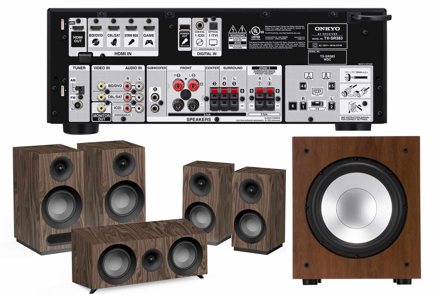
Настройка Cisco Nexus N3K-C3064PQ-10GX
Коммутатор имеет 48 портов SFP+ 10 Gb/s и 4 QSFP+ 40 Gb/s
При первом подключении через консоль, указываем пароль для пользователя admin:
Переключаемся в режим конфигурирования и указываем файл прошивки:
Сохранить конфигурацию, и перезагрузить коммутатор:
Далее смотрим текущую и сохраненную конфигурации:
Во время включении коммутатора при необходимости можно перейти в режим загрузчика:
Из загрузчика также можно вручную запустить коммутатор с указанной прошивки:
Выбрать режим портов, и после этого действия необходимо перезагрузить кошку:
hardware profile portmode ?
Добавим необходимые VLAN и при необходимости описания:
Настройка access и trunk портов:
Настройка гибридного порта, Vlan 100 без тага, а все остальные vlan с тагом:
По умолчанию порты 1-48 настроены на скорость 10 Gb/s, чтобы подключить 1 Gb/s нужно указать:
Часовой пояс и ntp сервер для синхронизации времени:
Если будут создаваться interface vlan (SVI), то нужно активировать feature interface-vlan:
Создание interface vlan (SVI):
Маршрут по умолчанию(default):
Настройка mgmt порта:
Можно указать hostname:
Разрешим использование SFP модулей от сторонних производителей:
При использовании сторонних SFP и DAC кабелей можно указать команды ниже для интерфейсов, так как без них либо не было линка, либо он пропадал через некоторое время, например:
Источник
Настройка и проверка значения максимального блока передачи данных на платформах Cisco Nexus
Параметры загрузки
Об этом переводе
Этот документ был переведен Cisco с помощью машинного перевода, при ограниченном участии переводчика, чтобы сделать материалы и ресурсы поддержки доступными пользователям на их родном языке. Обратите внимание: даже лучший машинный перевод не может быть настолько точным и правильным, как перевод, выполненный профессиональным переводчиком. Компания Cisco Systems, Inc. не несет ответственности за точность этих переводов и рекомендует обращаться к английской версии документа (ссылка предоставлена) для уточнения.
Содержание
Введение
В этом документе описывается настройка и проверка максимального блока передачи данных (MTU) на коммутаторах Cisco Nexus.
Предварительные условия
Требования
Для этого документа отсутствуют особые требования.
Используемые компоненты
Настоящий документ не имеет жесткой привязки к каким-либо конкретным версиям программного обеспечения и оборудования.
Настройка
Конфигурации MTU уровня 3
Все порты уровня 3 настраиваются индивидуально независимо от платформы.
Настройка MTU на коммутируемом виртуальном интерфейсе (SVI)
Настройте MTU на порте уровня 3
Конфигурации MTU уровня 2
MTU уровня 2 настраивается с использованием политики качества обслуживания (QoS) сети или путем настройки самого порта (на коммутаторах, поддерживающих настройку MTU на отдельных портах). Только Nexus 7000, 9000, и определенные 3000 моделей поддерживает для каждого порта MTU.
Настройка MTU для политики качества обслуживания сети
Nexus 3000: Включает коммутаторы серий Nexus 3048, 3064, 3132Q, 3132Q-X, 3132Q-XL, 3172 и 3500
Nexus 5000: Все коммутаторы серии Nexus 5000 и 5500
Nexus 6000: Все коммутаторы серии Nexus 6000
Чтобы настроить более высокое значение MTU на этих коммутаторах, создайте политику network-qos или измените существующую политику, чтобы задать более высокое значение MTU. Эта конфигурация применима ко всем портам. Она охватывает все порты Cisco Fabric Extender (FEX), подключенные к коммутатору. Настройка MTU на отдельных портах.
Настройка MTU на отдельных портах
Nexus 3000: Включает коммутаторы серии Nexus 3132Q-V, 3164, 31108, 31128PQ, 3200 и 36180YC-R
Neuxs 7000: Все коммутаторы серии Nexus 7000 и 7700
Nexus 9000: Все коммутаторы серии Nexus 9200 (включает 92xxx), 9300 коммутаторов Серии (включает 93xxx), и коммутаторы серии 9500
Для настройки MTU на для каждого порта основание, эта конфигурация необходима:
Настройка Nexus 2000
Примечание. Значение MTU для Nexus 2000 задается путем настройки кадров крупного размера на родительском коммутаторе. Для родительских коммутаторов, которые поддерживают кадры крупного размера для отдельных портов, следует настроить канал порта матрицы (FPC) FEX. Если для родительского коммутатора требуется политика качества обслуживания сети, в этом случае кадр крупного размера задается с использованием конфигурации политики качества обслуживания сети родительского коммутатора. Эти изменения в обоих случаях автоматически передаются в FEX.
Настройка FPC на отдельных портах (настраивается на родительском коммутаторе Nexus)
Примечание. Nexus 7000 не позволяет задать MTU FEX с использованием FPC в версии 6.2 и более поздних версий. Вместо этого необходимо создать пользовательскую политику качества обслуживания в соответствии со следующей конфигурацией.
Nexus 7000 / Конфигурация Кадра большого размера FEX (только применяется к версии 6.2 и позже),
Примечание. Измените текущий используемый шаблон. Чтобы найти текущий используемый шаблон, выполните команду show policy-map system type network-qos.
Настройка политики качества обслуживания сети (настраивается на родительском коммутаторе Nexus)
Проверка
Воспользуйтесь данным разделом для проверки правильности функционирования вашей конфигурации.
MTU уровня 3
Проверьте MTU уровня 3 на всех платформах Nexus с помощью команды show interface eth x/y, как показано в этом примере:
Проверьте MTU SVI с помощью команды show interface vlan, как показано в следующем примере вывода:
MTU уровня 2
В этом разделе описывается процедура проверки MTU уровня 2 для отдельных платформ. Команды выполняются с родительского коммутатора.
Проверьте MTU на коммутаторах то QoS сети использования
Проверьте MTU на коммутаторах та поддержка для каждого порта MTU
Примечание. Если Nexus 3000 в коде идет раньше, чем 7.0(3) I2(2a), необходимо проверить значение MTU с помощью команды ethernet show queueing interface x/x. Коммутаторы Nexus 3000, которые выполняют 7.0 (3) I2 (2a) и позже показывают максимальный размер передаваемого блока данных на для каждого порта основание.
Nexus 2000
Примечание. Если MTU FEX изменяется, значение MTU FEX увеличивается до более высокого предварительно определенного значения, которое не точно совпадает с заданным значением. Родительское устройство принудительно применяет настроенное значение MTU в канале порта матрицы (FPC) FEX.
Для FEX, связанного с Nexus 5000, 6000, и 7000:
Для FEX, связанного с Nexus 9000:
Устранение неполадок
Этот раздел обеспечивает информацию, которую вы можете использовать для того, чтобы устранить неисправность в вашей конфигурации.
Примечание.Перед использованием команд debug обратитесь к документу Важные сведения о командах отладки.
Иногда необходимо проверять изменения в программном обеспечении. Для этого проверьте диспетчер портов Ethernet (ethpm), чтобы убедиться в том, что изменения передаются программно на все платформы:
Кроме того, в модулях M1, M2, F1 и F2 можно проверить передачу изменений аппаратным способом:
Можно также просмотреть конфигурацию QoS на сетевой карте:
Влияние
Если обе стороны VPC не совпадают с MTU, несогласованный MTU через ссылку мог бы оказать влияние на маршрутизируемые интерфейсы с маршрутизацией смежностей и вызовет несоответствие типа 1 с VPC. Следует настраивать конфигурацию с осторожностью.
Дополнительные сведения о параметрах непротиворечивости VPC и Несоответствиях Типа 1 как MTU могут быть найдены в описании команды show vpc consistency-parameters.
Источник
Cisco Nexus 5000 Series NX-OS Software Configuration Guide
Book Title
Cisco Nexus 5000 Series NX-OS Software Configuration Guide
Chapter Title
Configuring the Switch
View with Adobe Reader on a variety of devices
View in various apps on iPhone, iPad, Android, Sony Reader, or Windows Phone
View on Kindle device or Kindle app on multiple devices
Results
Chapter: Configuring the Switch
Configuring the Switch
This chapter describes basic switch configuration functions. This chapter includes the following sections:
Image Files on the Switch
The Cisco Nexus 5000 Series switches have the following images:
- BIOS and loader images combined in one file
- Kickstart image
- System image that includes a BIOS image that can be upgraded
The switch has flash memory that consists of two separate flash parts:
- A 2 MB flash part holds two BIOS and loader images.
- A 1 GB flash part holds configuration files, kickstart images, systems images, and other files.
The upgradeable BIOS and the golden BIOS are programmed onto the 2 MB flash part. You cannot upgrade the golden BIOS.
When you download a new pair of kickstart and system images, you also get a new BIOS image because it is included in the system image. You can use the install all command to upgrade the kickstart, system, and upgradeable BIOS images.
This section includes the following topics:
Starting the Switch
A Cisco Nexus 5000 Series switch starts its boot process as soon as its power cord is connected to an A/C source. The switch does not have a power switch.
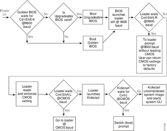
Boot Sequence
When the switch boots, the golden BIOS validates the checksum of the upgradeable BIOS. If the checksum is valid, then control is transferred to the upgradeable BIOS image. The upgradeable BIOS launches the kickstart image, which then launches the system image. If the checksum of the upgradeable BIOS is not valid, then the golden BIOS launches the kickstart image, which then launches the system image.
You can force the switch to bypass the upgradeable BIOS and use the golden BIOS instead. If you press Ctrl-Shift-6 within two seconds of when power is supplied to the switch, the golden BIOS will be used to launch the kickstart image, even if the checksum of the upgradeable BIOS is valid.

Note ![]() When you press Ctrl-Shift-6, the console settings must be set to their defaults: 9600 baud, 8 data bits, no parity, and 1 stop bit.
When you press Ctrl-Shift-6, the console settings must be set to their defaults: 9600 baud, 8 data bits, no parity, and 1 stop bit.
Before the boot sequence starts, the BIOS performs internal tests on the switch. If the tests fail, then the loader does not gain control. Instead, the BIOS image retains control and prints a message to the console at 9600 baud every 30 seconds that indicates a failure.
Figure 1-1 shows the normal and recovery boot sequence.
Figure 1-1 Boot Sequence
For information about recovery procedures, see Chapter1, “Troubleshooting”
Console Settings
The loader, kickstart, and system images have the following factory default console settings:
- Speed—9600 baud
- Databits—8 bits per byte
- Stopbits—1 bit
- Parity—none
These settings are stored on the switch, and all three images use the stored console settings.
To change a console setting, use the line console command in configuration mode. The following example configures a line console and sets the options for that terminal line:
switch# configure terminal switch(config)# line console switch(config-console)# databits 7 switch(config-console)# exec-timeout 30 switch(config-console)# parity even switch(config-console)# stopbits 2
You cannot change the BIOS console settings. These are the same as the default console settings.
Upgrading the Switch
Note ![]() Users with the network-admin role can upgrade the software image on the switch.
Users with the network-admin role can upgrade the software image on the switch.
This section includes the following topics:
Upgrade Procedure Summary
The following summary procedure describes how to upgrade the switch software:
Step 1 ![]() Log in to the console port on the supervisor module.
Log in to the console port on the supervisor module.
Step 2 ![]() Log in to Cisco.com and download the kickstart and system images to a server.
Log in to Cisco.com and download the kickstart and system images to a server.
Step 3 ![]() Download the kickstart and system images to the switch using the copy command.
Download the kickstart and system images to the switch using the copy command.
Step 4 ![]() Install the images using the install all command.
Install the images using the install all command.
 Caution While the switch performs the installation, all traffic through the switch is disrupted.
Detailed Upgrade Procedure
To upgrade the software on the switch, follow these steps:
Step 1 ![]() Log in to the switch on the console port connection.
Log in to the switch on the console port connection.
Step 2 ![]() Log in to Cisco.com to access the Software Download Center. To log in to Cisco.com, go to the URL http://www.cisco.com/ and click Log In at the top of the page. Enter your Cisco username and password.
Log in to Cisco.com to access the Software Download Center. To log in to Cisco.com, go to the URL http://www.cisco.com/ and click Log In at the top of the page. Enter your Cisco username and password.
Note ![]() Unregistered Cisco.com users cannot access the links provided in this document.
Unregistered Cisco.com users cannot access the links provided in this document.
Step 3 ![]() Access the Software Download Center using this URL:
Access the Software Download Center using this URL:
Step 4 ![]() Navigate to the software downloads for Cisco Nexus 5000 Series switches.
Navigate to the software downloads for Cisco Nexus 5000 Series switches.
You see links to the download images for the switch.
Step 5 ![]() Read the release notes for the related image file.
Read the release notes for the related image file.
Step 6 ![]() Select and download the kickstart and system software files to a server.
Select and download the kickstart and system software files to a server.
Step 7 ![]() Ensure that the required space is available in the bootflash: directory for the image file(s) to be copied.
Ensure that the required space is available in the bootflash: directory for the image file(s) to be copied.
switch# dir bootflash: 5910 Jun 17 14:48:28 2008 config0617 453 Jan 01 00:12:13 2005 ent-fm.lic 453 Jan 01 20:50:55 2005 ent-fm123.lic 453 Jan 01 20:58:49 2005 ent-fm123456.lic 215 Jan 01 00:13:50 2005 enterprise.lic 221 Jan 01 04:25:43 2005 eth-mod.lic 219 Jan 01 04:26:14 2005 eth-port.lic 216 Jan 01 00:21:48 2005 fc-feature.lic 49152 Jul 28 09:42:51 2008 lost+found/ 21581824 Jul 08 10:11:14 2008 n5000-uk9-kickstart.4.0.0.N1.1.445.bin 21573632 Jul 28 09:38:33 2008 n5000-uk9-kickstart.4.0.0.N1.1.47.bin 20062208 Jul 28 09:43:05 2008 n5000-uk9-kickstart.4.0.0.N1.2.467.bin 77139580 Jul 08 10:10:45 2008 n5000-uk9.4.0.0.N1.1.445.bin 75270834 Jul 28 09:38:33 2008 n5000-uk9.4.0.0.N1.1.47.bin 76924383 Jul 28 09:44:01 2008 n5000-uk9.4.0.0.N1.2.467.bin 4096 Jan 01 00:07:37 2005 routing-sw/ 3697 Apr 30 14:53:07 2008 startup-config 4096 Aug 08 12:49:09 2008 test/ 0 Jan 03 04:19:13 2005 thttpd_output 782893 Jan 21 16:56:14 2005 zone-scale-config.out 126927 Jan 21 16:55:45 2005 zoneset-scale-config.out Usage for bootflash://sup-local 855547904 bytes used 6942613504 bytes free 7798161408 bytes total 
Tip We recommend that you keep the kickstart and system image files for at least one previous software release to use if the new image files do not load successfully.
Step 8 ![]() If you need more space on the active supervisor module bootflash, delete unnecessary files to make space available.
If you need more space on the active supervisor module bootflash, delete unnecessary files to make space available.
switch# delete bootflash:n5000-uk9-kickstart.4.0.0.N1.1.445.bin switch# delete bootflash:n5000-uk9.4.0.0.N1.1.445.bin
Step 9 ![]() Copy the kickstart and system images to the supervisor module bootflash using a transfer protocol. You can use ftp:, tftp:, scp:, or sftp:. The examples in this procedure use scp:.
Copy the kickstart and system images to the supervisor module bootflash using a transfer protocol. You can use ftp:, tftp:, scp:, or sftp:. The examples in this procedure use scp:.
switch# copy scp://user@scpserver.cisco.com//downloads/n5000-uk9-kickstart.4.0.0.N1.2.bin bootflash:n5000-uk9-kickstart.4.0.0.N1.2.bin switch# copy scp://user@scpserver.cisco.com//downloads/n5000-uk9.4.0.0.N1.2.bin bootflash:n5000-uk9.4.0.0.N1.2.bin
Step 10 ![]() Install the new images, specifying the new image names that you downloaded in step 9.
Install the new images, specifying the new image names that you downloaded in step 9.
switch(config)# install all kickstart bootflash:n5000-uk9-kickstart.4.0.0.N1.2.bin system bootflash:n5000-uk9.4.0.0.N1.2.bin The install command performs the following actions:
- performs compatibility checks (equivalent to the show incompatibility command) for the images that you have specified. If there are compatibility issues, an error message is displayed and the installation does not proceed.
- Displays the compatibility check results and displays whether the installation is disruptive.
- Provides a prompt to allow you to continue or abort the installation.
Note ![]() A disruptive installation causes traffic disruption while the switch reboots.
A disruptive installation causes traffic disruption while the switch reboots.
- Updates the boot variables to reference the specified images and saves the configuration to the startup configuration file.
Step 11 ![]() After the switch completes the installation, log in and verify that the switch is running the required software version.
After the switch completes the installation, log in and verify that the switch is running the required software version.
switch# show version Cisco Nexus Operating System (NX-OS) Software TAC support: http://www.cisco.com/tac Copyright (c) 2002-2008, Cisco Systems, Inc. All rights reserved. The copyrights to certain works contained herein are owned by other third parties and are used and distributed under license. Some parts of this software may be covered under the GNU Public License or the GNU Lesser General Public License. A copy of each such license is available at http://www.gnu.org/licenses/gpl.html and http://www.gnu.org/licenses/lgpl.html Software BIOS: version 1.2.0 kickstart: version 4.0(0)N1(2) system: version 4.0(0)N1(2) BIOS compile time: 06/19/08 kickstart image file is: bootflash:/n5000-uk9-kickstart.4.0.0.N1.2.467.bin kickstart compile time: 7/28/2008 2:00:00 [07/28/2008 09:41:24] system image file is: bootflash:/n5000-uk9.4.0.0.N1.2.467.bin system compile time: 7/28/2008 2:00:00 [07/28/2008 10:09:17] Hardware cisco Nexus5020 Chassis («40x10GE/Supervisor») Intel(R) Celeron(R) M CPU with 2074164 kB of memory. Processor Board ID JAB120600AY bootflash: 7864320 kB nms-eugene-02 kernel uptime is 11 days 3 hours 15 minute(s) 19 second(s) Last reset at 63897 usecs after Mon Jul 28 09:46:39 2008 Reason: Reset by installer System version: 4.0(0)N1(1) Service:
Downgrading from a Higher Release
Note ![]() Only users with the network-admin role can downgrade the software image.
Only users with the network-admin role can downgrade the software image.
The procedure to downgrade the switch is identical to a switch upgrade, except that the image files to be loaded are for an earlier release than the image currently running on the switch.
Note ![]() Prior to downgrading to a specific release, check the release notes for the current release installed on the switch, to ensure that your hardware is compatible with the specific release.
Prior to downgrading to a specific release, check the release notes for the current release installed on the switch, to ensure that your hardware is compatible with the specific release.
To downgrade the software on the switch, follow these steps:
Step 1 ![]() Locate the image files you will use for the downgrade by entering the dir bootflash: command.
Locate the image files you will use for the downgrade by entering the dir bootflash: command.
If the image files are not stored on the bootflash memory, download the files from Cisco.com (using steps 1 through 9 of the software upgrade procedure).
Step 2 ![]() Install the new images.
Install the new images.
switch(config)# install all kickstart bootflash:n5000-uk9-kickstart.4.0.0.N1.1a.bin system bootflash:n5000-uk9.4.0.0.N1.1a.bin The install all command performs the following actions:
- performs compatibility checks (equivalent to the show incompatibility command) for the images that you have specified. If there are compatibility issues, an error message is displayed and the installation does not proceed.
- Displays the compatibility check results and displays whether the installation is disruptive.
- Provides a prompt to allow you to continue or abort the installation.
Note ![]() A disruptive installation causes traffic disruption while the switch reboots.
A disruptive installation causes traffic disruption while the switch reboots.
- updates the boot variables to reference the specified images and saves the configuration to the startup configuration file.
Step 3 ![]() After the switch completes the installation, log in and verify that the switch is running the required software version.
After the switch completes the installation, log in and verify that the switch is running the required software version.
switch# show version
Initial Configuration
The section includes the following topics:
Configuration Prerequisites
The following procedure is a review of the tasks you should have completed during hardware installation. These tasks must be completed before you can configure the switch.
Before you can configure a switch, follow these steps:
Step 1 ![]() Verify the following physical connections for the new Cisco Nexus 5000 Series switch:
Verify the following physical connections for the new Cisco Nexus 5000 Series switch:
- The console port is physically connected to a computer terminal (or terminal server).
- The management Ethernet port (mgmt0) is connected to an external hub, switch, or router.
Refer to the Cisco Nexus 5000 Series Hardware Installation Guide (for the required product) for more information.
Tip Save the host ID information for future use (for example, to enable licensed features). The host ID information is provided in the Proof of Purchase document that accompanies the switch.
Step 2 ![]() Verify that the default console port parameters are identical to those of the computer terminal (or terminal server) attached to the switch console port:
Verify that the default console port parameters are identical to those of the computer terminal (or terminal server) attached to the switch console port:
- 9600 baud
- 8 data bits
- No parity
- 1 stop bit
Initial Setup
The first time that you access a switch in the Cisco Nexus 5000 Series, it runs a setup program that prompts you for the IP address and other configuration information necessary for the switch to communicate over the Ethernet interface. This information is required to configure and manage the switch.
Note ![]() The IP address can only be configured from the CLI. When the switch powers up for the first time, you should assign the IP address. After you perform this step, the Cisco MDS 9000 Family Fabric Manager can reach the switch through the console port.
The IP address can only be configured from the CLI. When the switch powers up for the first time, you should assign the IP address. After you perform this step, the Cisco MDS 9000 Family Fabric Manager can reach the switch through the console port.
Preparing to Configure the Switch
Before you configure Cisco Nexus 5000 Series switch for the first time, you need the following information:
- Administrator password.
Note ![]() If a password is weak (short, easy-to-decipher), your password configuration is rejected. Be sure to configure a strong password.
If a password is weak (short, easy-to-decipher), your password configuration is rejected. Be sure to configure a strong password.
- If you are using an IPv4 address for the management interface, you need the following information:
– ![]() IPv4 subnet mask for the switch’s management interface.
IPv4 subnet mask for the switch’s management interface.
– ![]() IPv4 address of the default gateway (optional).
IPv4 address of the default gateway (optional).
- SSH service on the switch (optional).
To enable this service, select the type of SSH key (dsa/rsa/rsa1) and number of SSH key bits (768 to 2048).
- NTP server IPv4 address (optional).
- SNMP community string (optional).
- Switch name (optional).
This is your switch prompt.
- An additional login account and password (optional).
Note ![]() If you are using IPv4, be sure to configure the IPv4 route, the IPv4 default network address, and the IPv4 default gateway address to enable SNMP access.
If you are using IPv4, be sure to configure the IPv4 route, the IPv4 default network address, and the IPv4 default gateway address to enable SNMP access.
Default Login
The switch has the network administrator as a default user (admin). You cannot change the default user at any time.
There is no default password so you must explicitly configure a strong password. If a password is trivial (short, easy-to-decipher), your password configuration is rejected. Be sure to configure a strong password. If you configure and subsequently forget this new password, you have the option to recover this password.
Note ![]() If you enter a write erase command and reload the switch, you must reconfigure the default user (admin) password using the setup procedure.
If you enter a write erase command and reload the switch, you must reconfigure the default user (admin) password using the setup procedure.
Configuring the Switch
This section describes how to initially configure the switch.
Note ![]() Press Ctrl-C at any prompt to skip the remaining configuration options and proceed with what you have configured up to that point. Entering the new password for the administrator is a requirement and cannot be skipped.
Press Ctrl-C at any prompt to skip the remaining configuration options and proceed with what you have configured up to that point. Entering the new password for the administrator is a requirement and cannot be skipped.
Tip ![]() If you do not want to answer a previously configured question, or if you want to skip answers to any questions, press Enter. If a default answer is not available (for example, switch name), the switch uses what was previously configured and skips to the next question.
If you do not want to answer a previously configured question, or if you want to skip answers to any questions, press Enter. If a default answer is not available (for example, switch name), the switch uses what was previously configured and skips to the next question.
To configure the switch for first time, follow these steps:
Step 1 ![]() Ensure that the switch is on. Switches in the Cisco Nexus 5000 Series boot automatically.
Ensure that the switch is on. Switches in the Cisco Nexus 5000 Series boot automatically.
Step 2 ![]() Enter the new password for the administrator.
Enter the new password for the administrator.
Enter the password for admin: password
Tip If a password is weak (short, easy-to-decipher), your password configuration is rejected. Be sure to configure a strong password. Passwords are case-sensitive.
Step 3 ![]() Enter yes to enter the setup mode.
Enter yes to enter the setup mode.
This setup utility will guide you through the basic configuration of the system. Setup configures only enough connectivity for management of the system. *Note: setup is mainly used for configuring the system initially, when no configuration is present. So setup always assumes system defaults and not the current system configuration values. Press Enter at anytime to skip a dialog. Use ctrl-c at anytime to skip the remaining dialogs. Would you like to enter the basic configuration dialog (yes/no): yes
The setup utility guides you through the basic configuration process. Press Ctrl-C at any prompt to end the configuration process.
Step 4 ![]() Enter the new password for the administrator (admin is the default).
Enter the new password for the administrator (admin is the default).
Enter the password for admin: admin
Step 5 ![]() Enter yes (no is the default) to create additional accounts.
Enter yes (no is the default) to create additional accounts.
Create another login account (yes/no) [n]: yes
While configuring your initial setup, you can create an additional user account (in the network-admin role) besides the administrator’s account. See the “Configuring RBAC” section for information on default roles and permissions.
a. ![]() Enter the user login ID.
Enter the user login ID.
Enter the user login ID: user_name
b. ![]() Enter the user password.
Enter the user password.
Enter the password for user_name: user-password
Step 6 ![]() Enter yes (yes is the default) to create an SNMP read-only community string.
Enter yes (yes is the default) to create an SNMP read-only community string.
Configure read-only SNMP community string (yes/no) [n]: yes SNMP community string: snmp_community
Step 7 ![]() Enter a name for the switch.
Enter a name for the switch.
Note ![]() The switch name is limited to 32 alphanumeric characters. The default is switch.
The switch name is limited to 32 alphanumeric characters. The default is switch.
Enter the switch name: switch_name
Step 8 ![]() Enter yes (yes is the default) to configure out-of-band management.
Enter yes (yes is the default) to configure out-of-band management.
Continue with Out-of-band ( mgmt0) management configuration? [yes/no]: yes
a. ![]() Enter the mgmt0 IPv4 address.
Enter the mgmt0 IPv4 address.
Mgmt0 IPv4 address: ip_address
Step 9 ![]() Enter yes (yes is the default) to configure the IPv4 default gateway (recommended).
Enter yes (yes is the default) to configure the IPv4 default gateway (recommended).
Configure the default-gateway: (yes/no) [y]: yes
a. ![]() Enter the default gateway IPv4 address.
Enter the default gateway IPv4 address.
IPv4 address of the default-gateway: default_gateway
Step 10 ![]() Enter yes (yes is the default) to enable the Telnet service.
Enter yes (yes is the default) to enable the Telnet service.
Enable the telnet service? (yes/no) [y]: yes
Step 11 ![]() Enter yes (no is the default) to enable the SSH service.
Enter yes (no is the default) to enable the SSH service.
Enabled SSH service? (yes/no) [n]: yes
Step 12 ![]() Enter the SSH key type that you would like to generate.
Enter the SSH key type that you would like to generate.
Type the SSH key you would like to generate (dsa/rsa/rsa1)? dsa
Step 13 ![]() Enter the number of key bits within the specified range.
Enter the number of key bits within the specified range.
Enter the number of key bits? (768 to 2048): 768
Step 14 ![]() Enter yes (no is the default) to configure the NTP server.
Enter yes (no is the default) to configure the NTP server.
Configure NTP server? (yes/no) [n]: yes
a. ![]() Enter the NTP server IPv4 address.
Enter the NTP server IPv4 address.
NTP server IP address: ntp_server_IP_address
Step 15 ![]() Enter yes (yes is the default) to configure basic Fibre Channel configurations.
Enter yes (yes is the default) to configure basic Fibre Channel configurations.
Enter basic FC configurations (yes/no) [n]: yes
Step 16 ![]() Enter shut (shut is the default) to configure the default Fibre Channel switch port interface to the shut (disabled) state.
Enter shut (shut is the default) to configure the default Fibre Channel switch port interface to the shut (disabled) state.
Configure default physical FC switchport interface state (shut/noshut) [shut]: shut
Step 17 ![]() Enter on (on is the default) to configure the switch port trunk mode.
Enter on (on is the default) to configure the switch port trunk mode.
Configure default physical FC switchport trunk mode (on/off/auto) [on]: on
Step 18 ![]() Enter permit (deny is the default) to deny a default zone policy configuration.
Enter permit (deny is the default) to deny a default zone policy configuration.
Configure default zone policy (permit/deny) [deny]: permit
Permits traffic flow to all members of the default zone.
Note ![]() If you are executing the setup script after entering a write erase command, you explicitly must change the default zone policy to permit for VSAN 1 after finishing the script using the following command:
If you are executing the setup script after entering a write erase command, you explicitly must change the default zone policy to permit for VSAN 1 after finishing the script using the following command:
switch(config)# zone default-zone permit vsan 1
Step 19 ![]() Enter yes (no is the default) to enable a full zone set distribution.
Enter yes (no is the default) to enable a full zone set distribution.
Enable full zoneset distribution (yes/no) [n]: yes
Overrides the switch-wide default for the full zone set distribution feature.
You see the new configuration. Review and edit the configuration that you have just entered.
Step 20 ![]() Enter no (no is the default) if you are satisfied with the configuration.
Enter no (no is the default) if you are satisfied with the configuration.
The following configuration will be applied: username admin password role network-admin snmp-server community snmp_community ro switchname switch telnet server enable ssh key dsa 768 force ssh server enable system default switchport shutdown san system default switchport trunk mode on system default zone default-zone permit system default zone distribute full Would you like to edit the configuration? (yes/no) [n]: no
Step 21 ![]() Enter yes (yes is default) to use and save this configuration:
Enter yes (yes is default) to use and save this configuration:
Use this configuration and save it? (yes/no) [y]: yes Caution If you do not save the configuration at this point, none of your changes are updated the next time the switch is rebooted. Type yes to save the new configuration. This operation ensures that the kickstart and system images are also automatically configured (see “Image Files on the Switch” section).
Changing the Initial Configuration
To make changes to the initial configuration at a later time, enter the setup command in EXEC mode:
switch# setup —- Basic System Configuration Dialog —- This setup utility will guide you through the basic configuration of the system. Setup configures only enough connectivity for management of the system. *Note: setup is mainly used for configuring the system initially, when no configuration is present. So setup always assumes system defaults and not the current system configuration values. Press Enter at anytime to skip a dialog. Use ctrl-c at anytime to skip the remaining dialogs. Would you like to enter the basic configuration dialog (yes/no): yes
The setup utility guides you through the basic configuration process.
Accessing the Switch
After the initial configuration, you can access the switch in a number of ways:
- Serial console access—You can use a serial port connection to access the CLI.
- Out-of-band access—You can use Telnet or SSH to access a Cisco Nexus 5000 Series switch or use the Cisco MDS 9000 Fabric Manager application to connect to the switch using SNMP.
Additional Switch Configuration
This section includes the following topics:
Assigning a Switch Name
Each switch in the network requires a unique name. You can assign names to easily identify the switch by its physical location, its network association, or the organization to which it is deployed. The assigned name is displayed in the command-line prompt. The switch name is limited to 20 alphanumeric characters.
Note ![]() This guide refers to a switch in the Cisco Nexus 5000 Series switch as switch, and it uses the switch# prompt.
This guide refers to a switch in the Cisco Nexus 5000 Series switch as switch, and it uses the switch# prompt.
To change the name of the switch, perform this task:
| Command | Purpose | |||||||||||||||
|---|---|---|---|---|---|---|---|---|---|---|---|---|---|---|---|---|
| Command | Purpose | |||||||||||||
|---|---|---|---|---|---|---|---|---|---|---|---|---|---|---|
| switch# clock set HH:MM:SS DD Month YYYY |
| Command | Purpose | ||||||||||
|---|---|---|---|---|---|---|---|---|---|---|---|
| Command | Purpose | ||||||||
|---|---|---|---|---|---|---|---|---|---|
| Command | Purpose | ||||||
|---|---|---|---|---|---|---|---|
| Command | Purpose | ||||
|---|---|---|---|---|---|
| Command | Purpose | ||
|---|---|---|---|
| Command | Purpose |
|---|---|
| Command | Purpose |
|---|---|