Edge Tools
| Mode: | Edit Mode |
|---|---|
| Menu: | Mesh ‣ Edges |
| Hotkey: | Ctrl-E |
Make Edge/Face
| Mode: | Edit Mode |
|---|---|
| Panel: | Tool Shelf ‣ Tools ‣ Mesh Tools ‣ Add: Make Edge/Face |
| Menu: | Mesh ‣ Edges ‣ Make Edge/Face |
| Hotkey: | F |
It will create an edge or some faces, depending on your selection.
Set Edge Attributes
Edges can have several different attributes that affect how certain other tools affect the mesh.
Mark Seam and Clear Seam
| Mode: | Edit Mode |
|---|---|
| Menu: | Mesh ‣ Edges ‣ Mark Seam/Clear Seam |
Seams are a way to create separations, “islands”, in UV maps. See the UV Mapping section for more details. These operators set or unset this flag for selected edges.
Mark Sharp and Clear Sharp
| Mode: | Edit Mode |
|---|---|
| Menu: | Mesh ‣ Edges ‣ Mark Sharp/Clear Sharp |
The Sharp flag is used by the Edge Split Modifier , which is part of the smoothing techniques. As seams, it is a property of edges, and these operators set or unset it for selected ones.
Adjust Bevel Weight
| Mode: | Edit Mode |
|---|---|
| Menu: | Mesh ‣ Edges ‣ Edge Bevel Weight Properties Region ‣ Transform ‣ Edge Bevel Weight |
This edge property, a value between (0.0 to 1.0), is used by the Bevel Modifier to control the bevel intensity of the edges. This operator enters an interactive mode (a bit like transform tools), where by moving the mouse (or typing a value with the keyboard) you can set the bevel weight of selected edges. If two or more edge are selected, this operator alters the average weight of the edges.
Vertices also have a bevel weight which can be edited.
Edge Crease
| Mode: | Edit Mode |
|---|---|
| Menu: | Mesh ‣ Edges ‣ Edge Crease Properties Region ‣ Transform ‣ Edge Crease |
| Hotkey: | Shift-E |
This edge property, a value between (0.0 to 1.0), is used by the Subdivision Surface Modifier to control the sharpness of the edges in the subdivided mesh. This operator enters an interactive mode (a bit like transform tools), where by moving the mouse (or typing a value with the keyboard) you can set the (average) crease value of selected edges. A negative value will subtract from the actual crease value, if present. To clear the crease edge property, enter a value of -1.
Edge Slide
| Mode: | Edit Mode |
|---|---|
| Panel: | Tool Shelf ‣ Tools ‣ Mesh Tools ‣ Deform: Slide Edge |
| Menu: | Mesh ‣ Edges ‣ Slide Edge |
Slides one or more edges across adjacent faces with a few restrictions involving the selection of edges (i.e. the selection must define a valid loop, see below).
Even E Forces the edge loop to match the shape of the adjacent edge loop. You can flip to the opposite vertex using F . Use Alt-Wheel to change the control edge. Flipped F When Even mode is active, this flips between the two adjacent edge loops the active edge loop will match. Clamp Alt or C Toggle clamping the slide within the edge extents. Factor Determines the amount of slide performed. Negative values correspond to slides toward one face, while positive ones, refer to the other one. It is also displayed in the 3D View footer. Mirror Editing Lets you propagate the operation to the symmetrical elements of the mesh (if present, in local X direction). Correct UVs Corrects the corresponding UV coordinates, if these exist, to avoid image distortions.
Usage
By default, the position of vertices on the edge loop move as a percentage of the distance between their original position and the adjacent edge loop, regardless of the edges’ lengths.
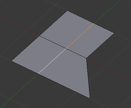
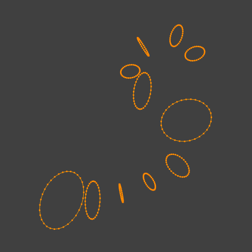
Selected edge loop.
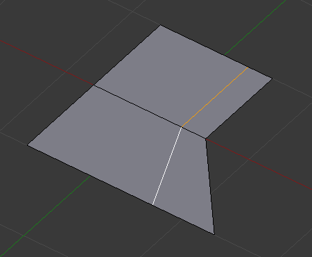
Repositioned edge loop.
Even Mode
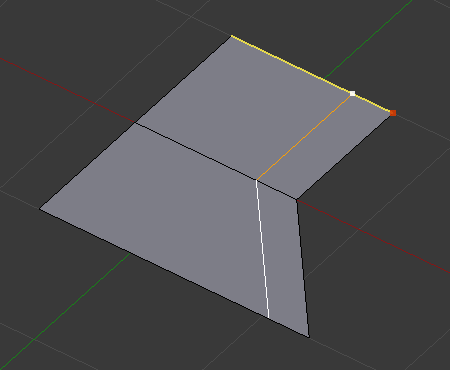
Even mode keeps the shape of the selected edge loop the same as one of the edge loops adjacent to it, rather than sliding a percentage along each perpendicular edge.
In Even mode, the tool shows the position along the length of the currently selected edge which is marked in yellow, from the vertex that as an enlarged red marker. Movement of the sliding edge loop is restricted to this length. As you move the mouse the length indicator in the header changes showing where along the length of the edge you are.
To change the control edge that determines the position of the edge loop, use the Alt-Wheel to scroll to a different edge.
Even Mode enabled.

Even Mode with Flip enabled.
Moving the mouse moves the selected edge loop towards or away from the start vertex, but the loop line will only move as far as the length of the currently selected edge, conforming to the shape of one of the bounding edge loops.
Limitations & Workarounds
There are restrictions on the type of edge selections that can be operated upon. Invalid selections are:
Loop crosses itself This means that the tool could not find any suitable faces that were adjacent to the selected edge(s). An example that shows this is selecting two edges that share the same face. A face cannot be adjacent to itself. Multiple edge loops The selected edges are not in the same edge loop, which means they do not have a common edge. You can minimize this error by always selecting edges end-to-end or in a “chain”. If you select multiple edges just make sure they are connected. This will decrease the possibility of getting looping errors. Border Edge When a single edge was selected in a single sided object. An edge loop cannot be found because there is only one face. Remember, edge loops are loops that span two or more faces.
A general rule of thumb is that if multiple edges are selected they should be connected end-to-end such that they form a continuous chain. This is literally a general rule because you can still select edges in a chain that are invalid because some of the edges in the chain are in different edge loops.
Rotate Edge
| Mode: | Edit Mode |
|---|---|
| Menu: | Mesh ‣ Edges ‣ Rotate Edge CW / Rotate Edge CCW |
Rotating an edge clockwise (CW) or counter-clockwise (CCW) spins an edge between two faces around their vertices. This is very useful for restructuring a mesh’s topology.
The tool operates on selected edges or the shared edge between selected faces.

Edge, rotated CW.
To rotate an edge based on faces you must select adjacent face pairs, otherwise Blender notifies you with an error message, “Could not find any select edges that can be rotated”. Using either Rotate Edge CW or Rotate Edge CCW will produce exactly the same results as if you had selected the common edge.
Edge Split
| Mode: | Edit Mode |
|---|---|
| Menu: | Mesh ‣ Edges ‣ Edge Split |
Edge Split is similar to the Rip tool. When two or more touching interior edges, or a border edge is selected when using Edge Split, a hole will be created, and the selected edges are duplicated to form the border of the hole.


Adjacent face moved to reveal hole left by split.
Bridge Edge Loops
| Mode: | Edit Mode |
|---|---|
| Menu: | Mesh ‣ Edges ‣ Bridge Edge Loops |
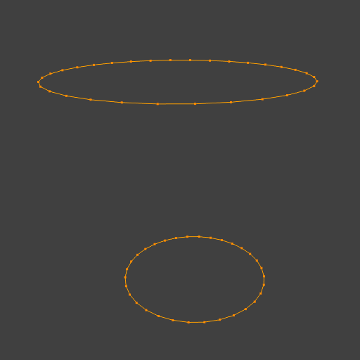
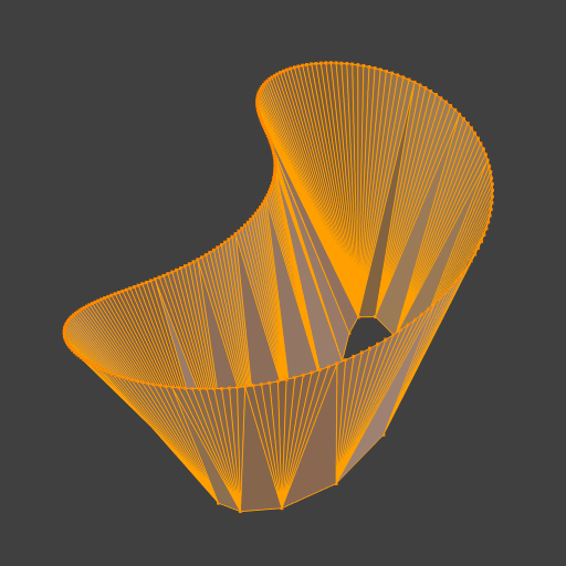
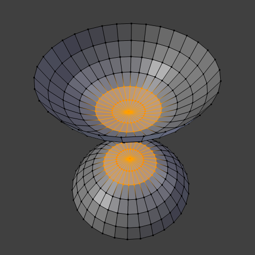
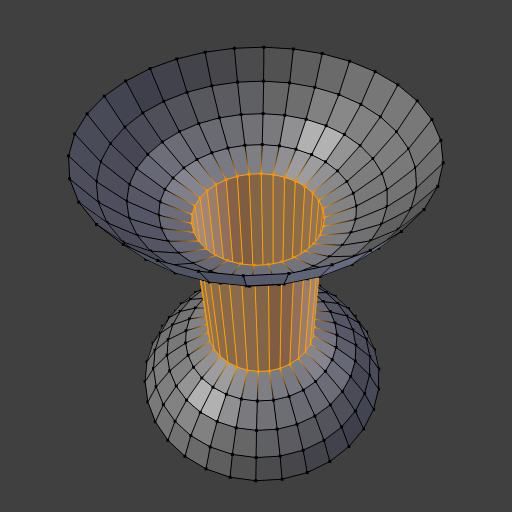
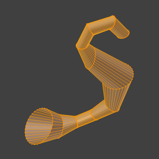
Bridge Edge Loops connects multiple edge loops with faces.
Connect Loops Open Loop Loops connected with open ends. Closed Loop Tries to connect to a circular loop (where start and end is merged). Loop pairs Connects each even count of loops individually. Merge Merges edge loops rather than creating a new face. Merge Factor Which edge loop the edges are merged to, a value of 0.5 will merge at a half-way point. Twist Determines which vertices in both loops are connected to each other. Number of Cuts The number of intermediate edge loops used to bridge the distance between two loops. Interpolation Linear, Blend Path, Blend Surface Smoothness Smoothness of the Blend Path and Blend Surface. Profile Factor How much intermediary new edges are shrunk/expanded. Profile Shape The shape of the new edges. See the proportional editing page for a description of each option.
Examples
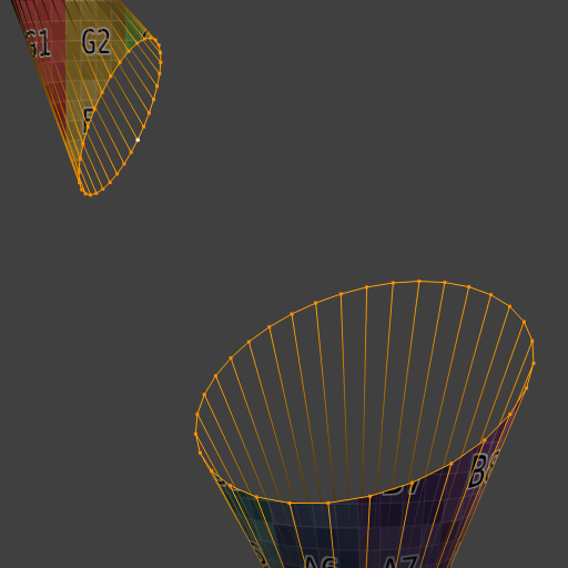
Simple example showing two closed edge loops.

Example of the Bridge tool between edge loops with different numbers of vertices.

Example using the Bridge tool to cut holes in face selections and connect them.
Example showing how Bridge tool can detect multiple loops and connect them in one step.
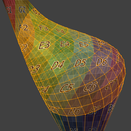
Example of the subdivision option and surface blending with UV’s.
© Copyright : This page is licensed under a CC-BY-SA 4.0 Int. License.
Источник
 uss_auriga
 uss_auriga
 Пакос Чивалдори
А я напишу без воды, вкратце:
01. AutoSmooth. 
Сглаживает все, у чего угол меньше, чем указанный (в данном случае 180) Работает только в блендере, вроде — UPD: неверно! При экспорте теряется, вроде. — UPD: неверно! Не нужен. Потому что ему на смену пришел другой модификатор UPD: неверно!
UPD: И я как обычно, ошибался 🙂 AutoSmooth в комбинации с Sharp Edge бывает, очень выручает.
Во-первых, он помогает справляться с традиционными проблемами острых граней при режиме отображения SmoothShading. А это офигенно потому, что в большинстве случаев с такой связкой мы и работаем в 3D.
Вот, наглядный пример кривого шейдинга из-за слишком острого угла между поверхностями при режиме отборажения SmoothShading
Здесь не помогает даже «пересчет грани» http://uss-auriga.livejournal.com/722780.html на Ctrl+T -> Alt+J
Из-за чего кстати, криво запеклись нормали и ужасно смотрятся, хотя HIGHPOLY в этом месте идеально ровная, но из-за проблем с шэйдингом у лоуполи, нормали выглядят так
И вот как это решается.
01. Включаем AutoSmooth
02. Выделяем грань и делаем ее острой Ctrl+E -> Mark Sharp
На картинке наша острая грань показана синими цветом
03. Все!
Вот как замечательно смотрится теперь LowPoly
И что еще важнее, вот как офигенно теперь запекаются нормали
То есть, Blender умеет экспортировать Sharp Edges в *.obj и что еще важнее, эти Sharp Edges понимает xNormal и мы получаем просто чудесные ровные плоские поверхности.
Хоу-хоу-хоу. Так что AutoSmooth и Sharp Edges очень-очень полезны бывают при рендере.
(В 3D Max’e их, кажется, называют TurboSmooth и SmoothGroups)
Вот тема https://blenderartists.org/forum/showthread.php?403523-Why-absolutely-flat-surface-looks-deformed-at-normal-map-texture
P.S. Кстати, я ведь отдерактировать нормали руками (просто залил «плоским цветом») и получилось тоже самое, надо было только шейдинг и геометрию поменять, проблема не в нормалях была. То есть, редактировать нормали руками, все же, можно, но очень осторожно.
02. Edge Split
Те же яйца только в профиль. Применяется вместе с командой Ctrl + E -> Mark Sharp
Дает больше контроля, потому что позволяет помечать любые грани как острые. Работает и вне блендера. Можно экспортировать модель в *.obj потом обратно и геометрия сохранится.
03. Команда W -> Shade Smooth и обратная W -> Shade Flat. Применяется (как вместе с Edge Split, так и без него) в режиме редактирования к выделенным полигонам. Если вдруг захотелось сделать какую-то часть модели сглаженной или плоской.
На картинке все это показано. Редим редактирования. На модельку применен Edge Split, синим показаны Sharp Edges, желтым выделены полигоны на которые применили W->Shade Flat
Вот что получилось. Объектный режим.
То есть, понятно как все работает.
В мануале дальше про модификаторы, но это уже нам известно.
Я лично делаю грани бевелом, потому при ретопологии и запекании карт достаточно просто снизить уровень сабдивайда у модели и получаем лоуполи.
Но иногда это вызывает гимор, потому что надо дополнительно пыхтеть над геотмерией, если мы хотим сохранить ее чистой и с квадами.
Поэтому надо попробовать с помощью модификатора Edge Split. По идее, он должен очень сильно облегчать работу, особенно когда надо редизайнить что-то много-много раз.
Источник